- 您现在的位置:买卖IC网 > Sheet目录868 > LTM8026MPV#PBF (Linear Technology)IC UMODULE 36VIN 5A CVCC 81LGA
�� �
�
�LTM8026�
�APPLICATIONS� INFORMATION�
�graphs� in� the� Typical� Performance� Characteristics� section�
�for� guidance.�
�The� maximum� frequency� (and� attendant� R� T� value)� at�
�which� the� LTM8026� should� be� allowed� to� switch� is� given�
�in� Table� 1� in� the� f� MAX� column,� while� the� recommended�
�frequency� (and� R� T� value)� for� optimal� efficiency� over� the�
�given� input� condition� is� given� in� the� f� OPTIMAL� column.�
�There� are� additional� conditions� that� must� be� satisfied� if�
�the� synchronization� function� is� used.� Please� refer� to� the�
�Switching� Frequency� Synchronization� section� for� details.�
�Capacitor� Selection� Considerations�
�The� C� IN� and� C� OUT� capacitor� values� in� Table� 1� are� the�
�minimum� recommended� values� for� the� associated� oper-�
�ating� conditions.� Applying� capacitor� values� below� those�
�indicated� in� Table� 1� is� not� recommended,� and� may� result�
�in� undesirable� operation.� Using� larger� values� is� generally�
�acceptable,� and� can� yield� improved� dynamic� response,� if�
�necessary.� Again,� it� is� incumbent� upon� the� user� to� verify�
�proper� operation� over� the� intended� system’s� line,� load� and�
�environmental� conditions.�
�Ceramic� capacitors� are� small,� robust� and� have� very� low� ESR.�
�However,� not� all� ceramic� capacitors� are� suitable.� X5R� and�
�X7R� types� are� stable� over� temperature,� applied� voltage� and�
�give� dependable� service.� Other� types,� including� Y5V� and�
�Z5U� have� very� large� temperature� and� voltage� coefficients�
�of� capacitance.� In� an� application� circuit� they� may� have� only�
�a� small� fraction� of� their� nominal� capacitance� resulting� in�
�much� higher� output� voltage� ripple� than� expected.�
�Many� of� the� output� capacitances� given� in� Table� 1� specify�
�an� electrolytic� capacitor.� Ceramic� capacitors� may� also� be�
�used� in� the� application,� but� it� may� be� necessary� to� use�
�more� of� them.� Many� high� value� ceramic� capacitors� have� a�
�large� voltage� coefficient,� so� the� actual� capacitance� of� the�
�component� at� the� desired� operating� voltage� may� be� only�
�a� fraction� of� the� specified� value.� Also,� the� very� low� ESR� of�
�ceramic� capacitors� may� necessitate� additional� capacitors�
�for� acceptable� stability� margin.�
�A� final� precaution� regarding� ceramic� capacitors� concerns�
�the� maximum� input� voltage� rating� of� the� LTM8026.� A�
�ceramic� input� capacitor� combined� with� trace� or� cable�
�inductance� forms� a� high� Q� (under� damped)� tank� circuit.�
�If� the� LTM8026� circuit� is� plugged� into� a� live� supply,� the�
�input� voltage� can� ring� to� twice� its� nominal� value,� possi-�
�bly� exceeding� the� device’s� rating.� This� situation� is� easily�
�avoided;� see� the� Hot� Plugging� Safely� section.�
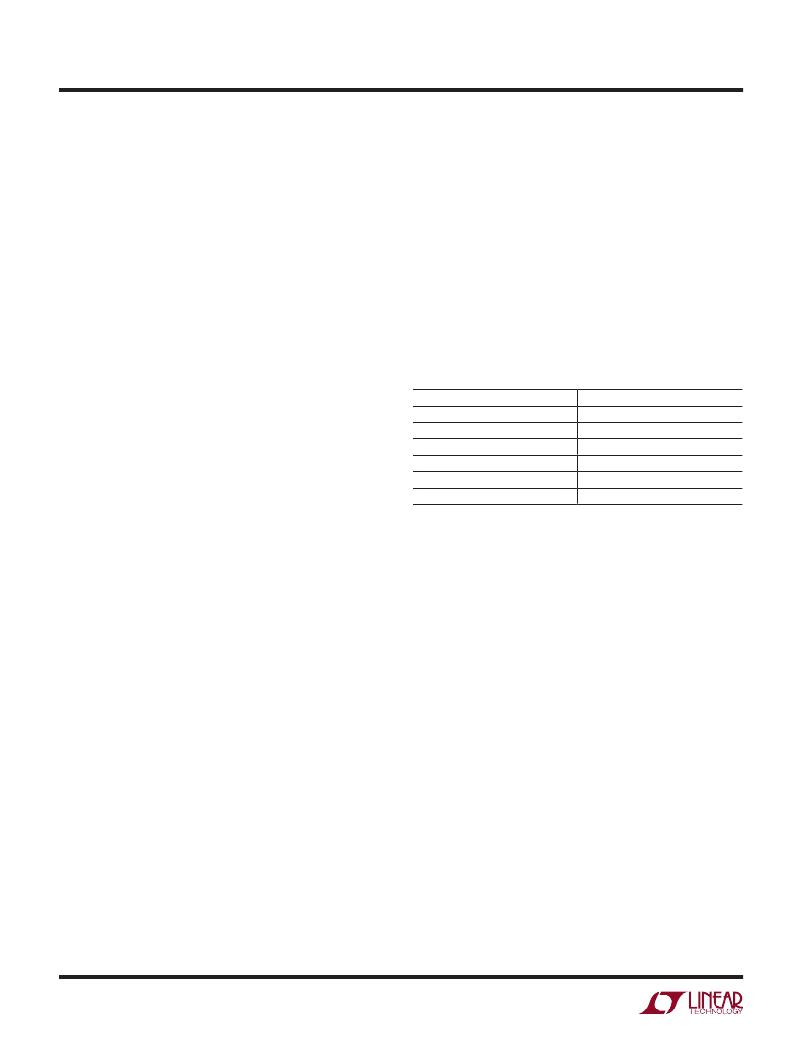
�Programming� Switching� Frequency�
�The� LTM8026� has� an� operational� switching� frequency�
�range� between� 100kHz� and� 1MHz.� This� frequency� is�
�programmed� with� an� external� resistor� from� the� RT� pin� to�
�ground.� Do� not� leave� this� pin� open� under� any� circumstance.�
�See� Table?� 2� for� resistor� values� and� the� corresponding�
�switching� frequencies.�
�Table� 2.� R� T� Resistor� Values� and� Their� Resultant� Switching�
�Frequencies�
�SWITCHING� FREQUENCY� (MHz)� R� T� (kΩ)�
�1� 39.2�
�0.750� 53.6�
�0.5� 82.5�
�0.3� 140�
�0.2� 210�
�0.1� 453�
�In� addition,� the� Typical� Performance� Characteristics� sec-�
�tion� contains� a� graph� that� shows� the� switching� frequency�
�versus� R� T� value.�
�To� improve� efficiency� at� light� load,� the� part� will� enter�
�discontinuous� mode.�
�Switching� Frequency� Trade-Offs�
�It� is� recommended� that� the� user� apply� the� optimal� R� T�
�value� given� in� Table� 1� for� the� input� and� output� operating�
�condition.� System� level� or� other� considerations,� however,�
�may� necessitate� another� operating� frequency.� While� the�
�LTM8026� is� flexible� enough� to� accommodate� a� wide� range�
�of� operating� frequencies,� a� haphazardly� chosen� one� may�
�result� in� undesirable� operation� under� certain� operating� or�
�fault� conditions.� A� frequency� that� is� too� high� can� reduce�
�efficiency,� generate� excessive� heat� or� even� damage� the�
�LTM8026� in� some� fault� conditions.� A� frequency� that� is� too�
�low� can� result� in� a� final� design� that� has� too� much� output�
�ripple� or� too� large� of� an� output� capacitor.�
�Switching� Frequency� Synchronization�
�The� nominal� switching� frequency� of� the� LTM8026� is�
�determined� by� the� resistor� from� the� RT� pin� to� GND� and�
�8026fb�
�14�
�For� more� information� www.linear.com/LTM8026�
�发布紧急采购,3分钟左右您将得到回复。
相关PDF资料
LTM8027EV#PBF
IC BUCK SYNC ADJ 4A 113LGA
LTM8032MPY#PBF
IC DC/DC UMODULE 2A 71BGA
LTM8033MPV#PBF
IC DC-DC UMODULE BUCK 3A 76-LGA
LTM8040IV#PBF
IC LED DRVR HP CONST CURR 66-LGA
LTM8042IV#PBF
IC UMODULE LED DRIVER 56LGA
LTM8048MPY#PBF
IC DC/DC UMODULE LDO BGA
LTM8052AEV#PBF
IC UMODULE 36VIN 5A CVCC 81LGA
M30R224K5
CAP CER 0.22UF 50V 10% RADIAL
相关代理商/技术参数
LTM8027
制造商:LINER 制造商全称:Linear Technology 功能描述:60V、4A DC/DC μModule 穩壓器
LTM8027EV
制造商:LINER 制造商全称:Linear Technology 功能描述:60V, 4A DC/DC Module Regulator
LTM8027EV#PBF
功能描述:IC BUCK SYNC ADJ 4A 113LGA RoHS:是 类别:电源 - 板载 >> DC DC Converters 系列:µModule® 设计资源:VI-200, VI-J00 Design Guide, Appl Manual 标准包装:1 系列:* 类型:隔离 输出数:1 电压 - 输入(最小):66V 电压 - 输入(最大):160V Voltage - Output 1:12V Voltage - Output 2:- Voltage - Output 3:- 电流 - 输出(最大):* 电源(瓦) - 制造商系列:50W 电压 - 隔离:* 特点:* 安装类型:通孔 封装/外壳:9-FinMod 尺寸/尺寸:4.60" L x 1.86" W x 0.79" H(116.8mm x 47.2mm x 20.1mm) 包装:散装 工作温度:-25°C ~ 85°C 效率:* 电源(瓦特)- 最大:*
LTM8027EV#PBF
制造商:Linear Technology 功能描述:DC/DC Converter IC 制造商:Linear Technology 功能描述:IC, STEP-DOWN DC/DC MODULE REG, LGA-113
LTM8027EVPBF
制造商:Linear Technology 功能描述:DC/DC Regulator 4A 60Vin 2.5-24Vout
LTM8027IV
制造商:LINER 制造商全称:Linear Technology 功能描述:60V, 4A DC/DC Module Regulator
LTM8027IV#PBF
功能描述:IC BUCK SYNC ADJ 4A 113LGA RoHS:是 类别:电源 - 板载 >> DC DC Converters 系列:µModule® 设计资源:VI-200, VI-J00 Design Guide, Appl Manual 标准包装:1 系列:* 类型:隔离 输出数:1 电压 - 输入(最小):21V 电压 - 输入(最大):32V Voltage - Output 1:5V Voltage - Output 2:- Voltage - Output 3:- 电流 - 输出(最大):* 电源(瓦) - 制造商系列:100W 电压 - 隔离:* 特点:* 安装类型:通孔 封装/外壳:9-SlimMod 尺寸/尺寸:4.60" L x 1.80" W x 0.52" H(116.8mm x 45.7mm x 13.2mm) 包装:散装 工作温度:-25°C ~ 85°C 效率:* 电源(瓦特)- 最大:*
LTM8027IV#PBF
制造商:Linear Technology 功能描述:DC/DC Converter IC